

The ESP-01S is easy to sleep. The ESP.deepsleep() function put the device into a very low-power sleep mode. The challenge is waking it up again!
The most common method appears to be to solder a wire link between pin-8 of the ESP8266 processor (the ‘XDP-DCDC’ pin) to the reset pin on the header. When the ESP.deepSleep() period expires, the pin toggles the reset and that restarts the ESP-01S device.
The issue is that the pins on the ESP8266 IC are tiny, and although pin-8 is on the corner, it is nonetheless very tricky to solder a wire to that pin. People do this and it can work OK for sure. But I have found the solder connection to be quite tricky to make and a bit fragile – and hence unreliable. At least for me.
It is a shame that the ‘XDP-DCDC’ pin is not made more readily accessible on the PCB of the EPS-01S. But it isn’t.
A different way to tackle the challenge
I use a different technique. In essence, I forget the ‘XDP-DCDC’ pin altogether. I use an external trigger to wake the ESP8266 with the reset pin. And I do that externally using an ATTINY85.
The nice thing about using an ATTINY85 is that not only can it also be put into very low-power sleep but it can wake itself up. All I did was to connect an IO pin of the ATTINY85 to the Reset pin of the EPS-01S, and use the ATTINY85 to wake the EPS-01S. Essentially, wake the ATTINY85, and raise the IO pin from low to high , and the ESP-01S wakes up.
My project
I wanted to monitor the temperature and humidity in an external building using a battery powered monitor. I used a HDT22 module designed for an ESP-01S. This assembly posts temperature and humidity data to a web server every hour. Otherwise the ESP must be in sleep mode to save batter power. The hourly sequence is:
- The ATTINY85 wakes up and resets the ESP-01S by raising the rest pin to high
- The ESP-01S wakes up, connects to the WiFi, reads the temperature and humidity, posts the data, then goes back to sleep
- The ATTINY85 goes back to sleep for an hour.
The sequence repeats every hour.
No loop()
In my Arduino sketch, all of the processing in done in the setup() section, the last command being ESP.deepSleep(0). The (0) says to stay asleep without a timeout (forever, until reset).
Hence the loop() never executes. So the setup() becomes the hourly loop()! Of course you could still use the loop(), but in this case it wasn’t necessary.
Waking the ATTINY85
I used a library called TinySnore by Connor Nishijima (credit and thanks to Connor). This library is terrific, and it is very easy to use. You use it like delay() – actually you say “snore()” with the mS sleep time as the parameter e.g. ‘snore(10000);’ to sleep for 10 seconds.
Project details
It’s a very simple circuit. Pin-2 of the ATTINY85 (which is GPIO3) is connected to the Reset pin of the ESP-01, via a 100R resistor. That’s it!
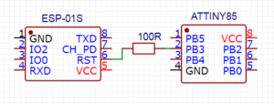
The 100R resistor is there to protect the output of the ATTINY85 – the HDT22 module I used has a reset button (connected to the reset pin). If the reset button is pressed when the GPIO pin goes high, the high signal on the ATTINY85 would be shorted to GND. With a 3.3V supply, the 100R resistor limits the current to 33mA under those circumstances which is within the specification of the ATTINY85.
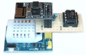
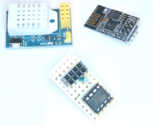
So, the project ends up with 3 parts: the ATTINY85, ESP-01S and the HDT22 module. The 3.7V Li-ion battery is connected to the supply connections on the HDT22 module (which has a 3.3V regulator).
I created an intermediate PCB to hold the ATTINY85. The three elements and the final assembly are shown below.
The HDT22 module has an improved specification over the more frequently used HDT11. However, a HDT11 module could be used. You don’t have to use the module of course – you can home-brew your own circuit using a simple HDT22 or HDT11 sensor. But in this case we wanted to run from a Li-ion cell so some regulator was needed anyway.
Power consumption
When asleep the ESP-01S consumes around 20uA, and the ATTINY85 consumes around 5uA. There is a power LED on the HDT module that consumes around 3mA, so that will be removed! There are other passive components plus a 3.3V regulator which of course are necessary for this project.
I am yet to determine how long the Li-ion battery will run. I will update this article as and when I have more results to share.
Summary
I know! – soldering a wire link from a pin on the ES8266 chip to the Reset header pin is perfectly doable. But it wasn’t the best solution for me. I spent a small amount to achieve something that I think represents an improved solution over the wire link.
And it’s easy to do…
If you want to try
If we have stock, you can buy the components here, as we think we offer great prices. Otherwise you can shop from your usual supplier.
If you want to buy here, you can, and that would be nice thanks. But our limited stocks do sell quite fast. Anyway, here are the links: