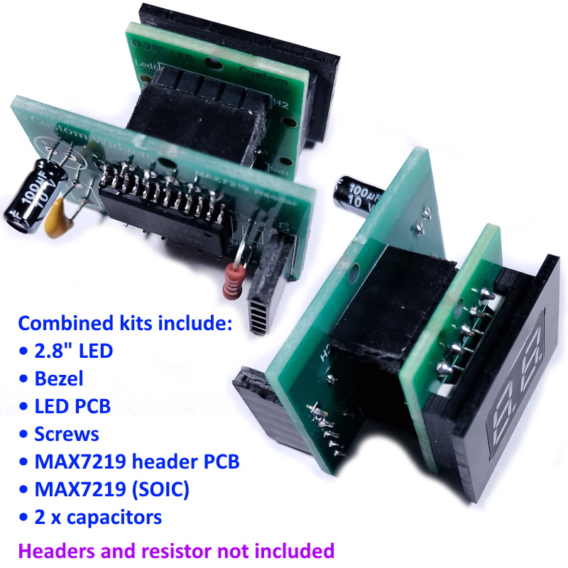
Description
This item comprises two separate kits that may be connected together:
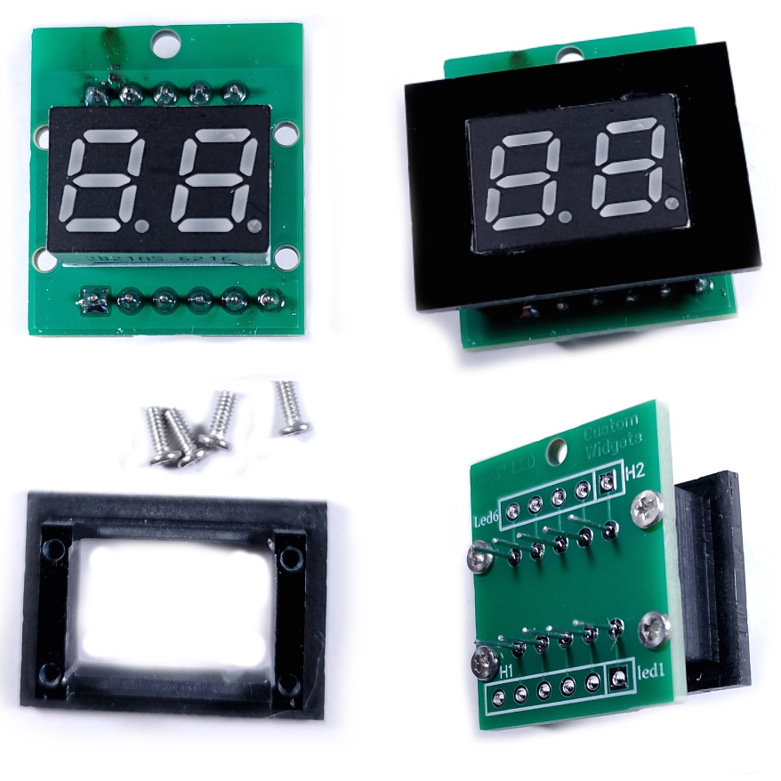
- A 0.28″ LED, Bezel and PCB. This kit allows you to mount one of these tiny LED displays to your panel or enclosure. The bezel overlaps the front panel by approximately 2mm all round to hide the edges of your cut-out, and is attached to the rear with adhesive (not supplied). The result is a very professional-looking display without ugly, visible mounting screws. There is a ground (GBD) backplane not connected to any LED pad.
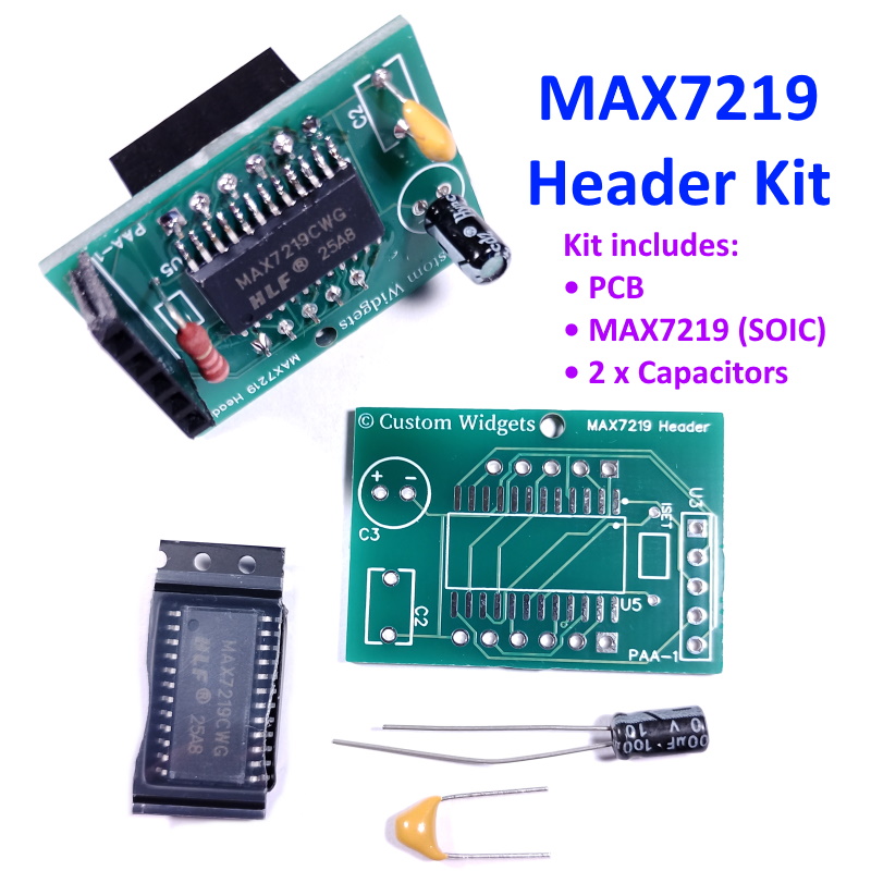
- A MAX7219 Driver kit, designed to fit the 0.28″ kit, but this kit can also be used as a LED driver for other projects. This is a very small driver kit that can be directly connected to (or plugged onto, using appropriate headers) the 0.28″ LED/Bezel assembly. The driver kit requires only 5 external connections, so making it easy to create an LED display. This kit removes the need to incorporate LED driver ICs in your project. The PCB has a ground (GND) backplane which extends to the LED PCB.
Kit Detail
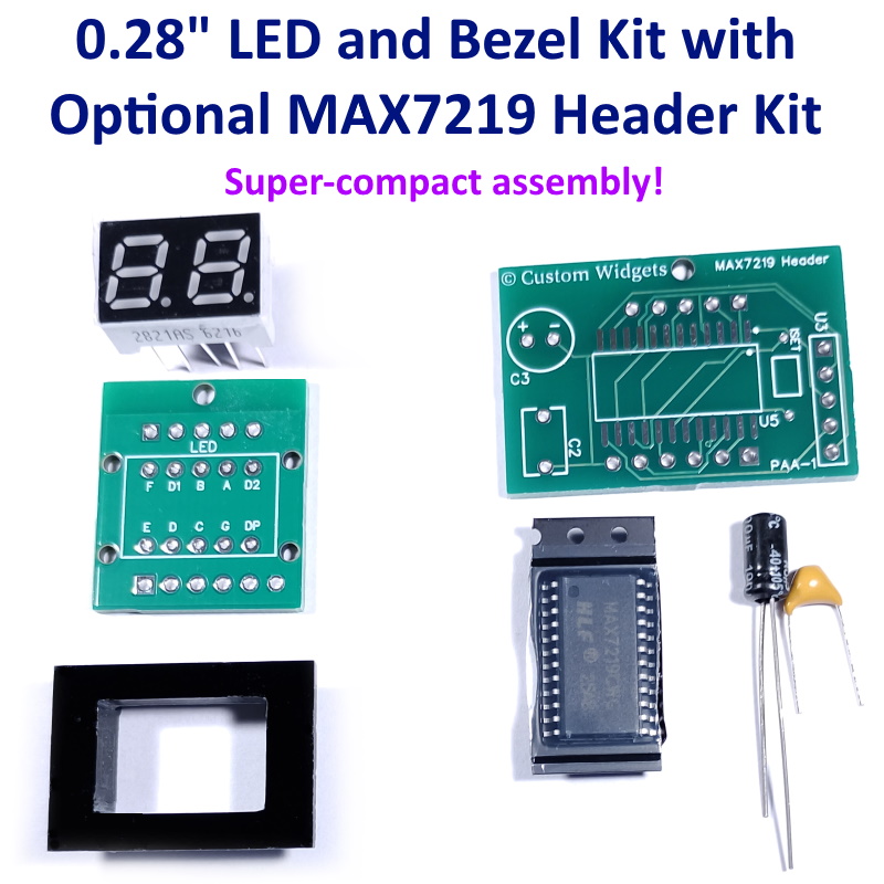
- The 0.28″ LED kit comprises a 2-digi LED 7–segment display, a Bezel, a PCB to attach the LED to the Bezel, and attachment screws.
- The MAX7219 kit comprises a MAX7219 IC in SOIC format, a PCB, and two capacitors. To use this kit, you will need to be comfortable soldering SOIC devices, and you will need to add a suitable resistor to set the LED current (see the MAX7219 datasheet for instructions on how to set the resistor value).
- There are no headers in either kit, and you can either use directly soldered wiring or add you own headers to suit your project. We sell headers if you need them, which you can cut to size.
- These kits are supplied as KITS OF PARTS, which you need to solder and assemble yourself. Full instructions are included with each kit.
- Both of the PCBs in these kits have a 2mm hole at the top. When assembled, they are aligned so that a plastic offset/spacer and screws can be use to provide a mechanical fixing between the two kits, intended to hold the driver kit in position against the bezel kit. This attachment is not intended for any weight heaver that the driver kit.
Bezel Details
- Dimensions 24.1mm wide, 17.1mm tall, approx 6mm thick.
- Colour: high-quality, glossy black front and machined edges and rear.
- The bezel does not have any Ingress Protection ratings.
- The PCB is attached on the rear of the bezel with the screws provided.
LED Details
- LED: 0.28″ red.
- Model 2821AS 2-digit with decimal point.
- Common Cathode.
- We test ALL LED Displays before dispatch.
MAX7219 driver details
- Incorporates a SOIC Maz7219 resulting in a small and compact driver assembly.
- PCB dimensions: 33mm x 23mm.
- Assembled weight (as supplied), approx 4g.
- Kit thickness, including IC but not headers or capacitors: Approx 4.5mm. With the supplied electrolytic capacitor is is about 11mm thick.
- The ceramic capacitor is a 0.1uf bypass capacitor.
- Note: we supply a 100uf/10V capacitor, but you may wish or need to use a different value based on your project designs.
- We don’t supply the resistor to set the LED current. You will need to determine your own value based on the maximum brightness you are designing (see the datasheet for details).
Dimensions are nominal/approximate.
Please note that, given the wide variety of designs and projects, we do not provide design or technical services. You must have suitable electronics, soldering, and programming skills to make use of this kit.
If you need standard headers that you can cut to size, we offer these Standard Headers